


Understanding the principles of various flowmeters is crucial for fluid monitoring. This article introduces the working principles of multiple flowmeters. These flowmeters utilize different physical phenomena and technologies and can be used for various fluid measurements.
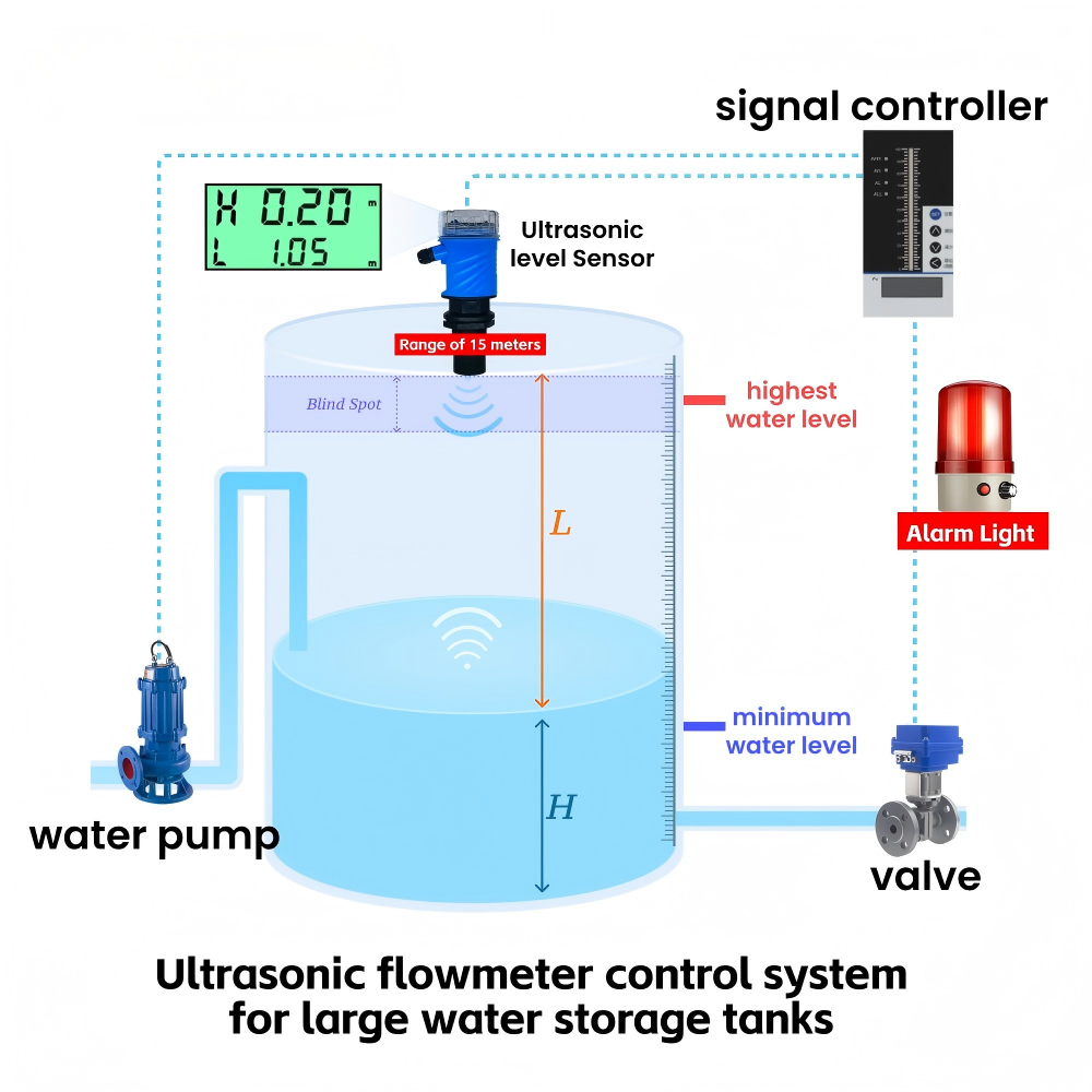
1.Ultrasonic flowmeter
Probes (sensors) are installed on both sides outside the pipe wall. When ultrasonic waves are transmitted between the probes on both sides, a time difference proportional to the flow velocity is generated between the two directions of downstream and upstream, and the flow rate is calculated based on this.

2. Electromagnetic Flowmeter
An electromagnetic flowmeter applies the principle of electromagnetic induction to measure the flow rate of a conductive fluid based on the electromotive force generated when the conductive fluid passes through an external magnetic field. A coil is installed above the pipeline to generate a magnetic field. The fluid must contain charged ionic substances. When the fluid passes through, it deflects in the magnetic field, generating an electromotive force between the two sides of the pipe. The electromotive force is proportional to the average flow velocity, and the flow rate is measured through calculation.

3.Vortex Flowmeter
Vortex flowmeter is a fluid oscillation flow meter based on the Karman vortex street principle. A non-streamlined vortex generator is placed vertically in the pipeline. When the fluid reaches a certain flow velocity, alternately shedding vortices will be generated downstream of the generator. The vortex shedding frequency is proportional to the average flow velocity of the fluid, and the volume flow rate of the fluid can be calculated by detecting the frequency.

4.Thermal Mass Flow Meter
Thermal mass flowmeters utilize the principle of thermal diffusion: two temperature sensors are placed in the fluid, one of which is heated, and the other is used to measure the medium temperature. When the fluid flows, it will carry away heat, causing a change in the temperature difference/heating power between the two sensors. This change is proportional to the gas mass flow rate, thereby directly measuring the mass flow rate.

5. Differential pressure flowmeter
When fluid flows through a throttle element (such as an orifice plate, nozzle, Venturi tube) in a pipeline, the flow beam contracts, the flow velocity accelerates, and the static pressure decreases, forming a pressure difference ΔP before and after the throttle element. Under certain conditions, the flow rate is proportional to the square root of the differential pressure, and the volumetric flow rate or mass flow rate can be obtained by measuring the differential pressure.